I have made the worm and wheel for the orrery twice before. The second time the wheel dropped from 52 teeth to 26. This implies one turn of the crank advances the orrery two weeks. The second pair were made out of aluminum. I would like to remake them out of brass. When the handle is turned the aluminum worm and wheel grind as they turn. This is due to the angle of the threads cut into the wheel. I measured and calculated the threads of the worm at a 5.7° angle. When I cut the wheel with this angle the two do not fit well!?!
Rethinking the calculations: The adjacent side of the appropriate triangle should be the circumference of the worm. The thread shifts 0.1047" for each turn of the worm. A turn of the worm is 0.5π. So the correct formula should be as follows: tan-1(0.1047/0.5π) = 3.8°!
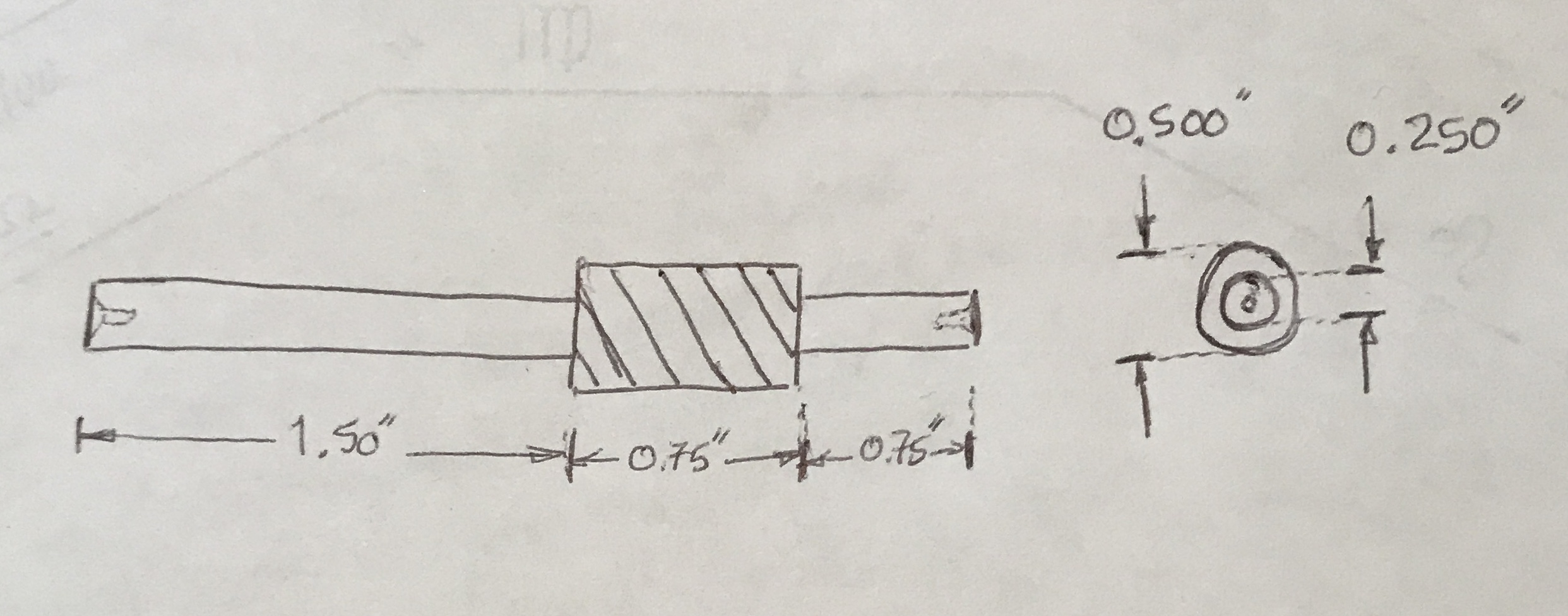
The wheel with 26 teeth will be cut using a 30 DPI cutter. The PD is then 26/30 = 0,867". And the OD = 26+2/30 = 0.933". The center hole needs to be reamed 0.25" diameter. The wheel should be 1/4" thick. The pitch of the 26 tooth wheel is CP = pi/30 = 0.1047". This equates to 9.55 TPI. So this is the pitch for the worm as well. To cut a 9.5 TPI thread on the Sherline the gears for a 19 TPI thread are used with the 100-teeth "B" gear replaced by a 50-teeth gear. My cutters have a 14.5° PA so the worm needs to match. I will use a 30° (vs. 29) included angle cutting tool to cut the worm. Finally, the milling head needs to be rotated counterclockwise 3.8°± to produce the mating threads for the worm. The simple plan for the worm is shown below.
I needed to look up the number of the cutter to use for the 26 tooth gear. A number 4 cuts 26-34. I have included the following table to make this simpler to find in the future. Or I could have used the Spur Gears calculation tool listed just to the left.
| Cutter Number vs. Number of Teeth for Involute Gears | ||||||||
|---|---|---|---|---|---|---|---|---|
| Cutter Number | 1 | 2 | 3 | 4 | 5 | 6 | 7 | 8 |
| Number of Teeth | 135 to rack | 55-134 | 35-54 | 26-34 | 21-25 | 17-20 | 14-16 | 12-13 |
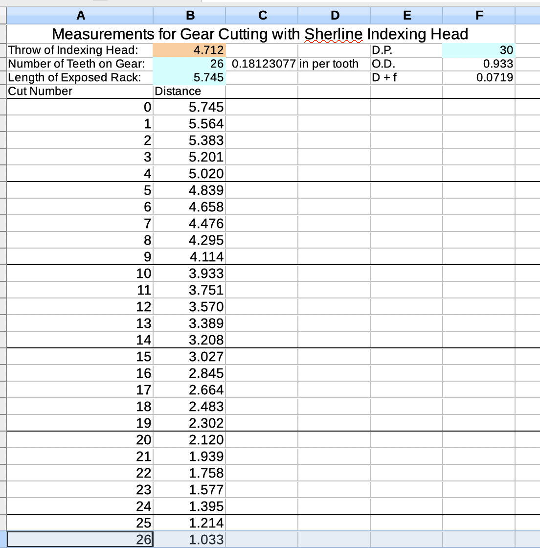
To cut the gear with the Sherline gear cutting attachment the length of the rack is adjusted for each successive cut. A spreadsheet was used to calculate these lengths, Metalworking/Gear Cutting/Gear Cutting Measurements.ods. The length of the exposed rack is 5.745". The depth of cut is 0.072" for a 30 DP gear. The headstock was set at 3.8° as measured by HandyLevel on the iPhone. The cutter was adjusted to be at the top of the gear blank with the aid of a ruler and the phone level. It was then lowered 0.466" to be on center. It was difficult to adjust the cutter so as to be on center from left to right. The cutter was advanced directly into the blank 0.072". The blank was then rotated according to the chart below and another cut was made. When all cuts were complete the gear was moved back to the lathe for cleanup with a file. The cuts were not symmetrical. The top of each tooth was wider on one end than the other. An attempt was made to correct this with a three corner file. This was clearly a result of the cutter not being centered left/right. Should have "found" the side of the wheel blank with the cutter and then moved it over the cutter radius plus the wheel radius.
A 3" length of 1/2" brass round was found in the scrap pile. It was held in the 3-jaw chuck and faced. It was center drilled and the live center was used while 1.5" was reduced to 0.250" diameter. The shaft was checked to make sure it easily slid through a 0.250" reamed hole. The part was removed from the chuck and the newly reduced end was held in a 1/4" collet. This way all succeeding operations would be concentric with the already reduced end. The other end was faced and center drilled. This end was supported by the half tail stock support. It was reduced to 0.250" for a length of 0.75". Again the newly cut shaft was checked for fit prior to proceeding. The remaining 0.75" of 1/2" stock between the two 1/4" shafts was lightly sanded up to 1500 grit just to clean it up. Both ends of this 1/2" section were heavily chamfered.
The lathe was set up for thread cutting only to discover that when the 100 tooth "B" gear is substituted by a 50 tooth gear the handle of the thread cutting attachment cannot go all the way onto the spindle. This gear substitution is needed so the gear setup for 19 TPI can be used on this worm that requires 9.5 TPI. I had previously made a collar for this exact purpose, but could not find it. I did find a 7/16" length of 1" brass round that had an approximately 1/2" hole in the center. It was a slightly loose fit over the spindle. This tube was held in the vise on the mill and its length was reduced to 13/32" with the two-insert cutter. A small divot was cut on the inside edge with a 3/16" end mill. The divot was 1/16" deep (relative to the tube's axis) and went 3/32" into the wall of the tube. The tube was flipped end for end and a #50 drill was used to make a hole for a stem the handle could bite on. The hole was drilled about 1/4" deep and threaded 2-56. A small 2-56 screw was cut off and the cut off piece was screwed into the hole leaving about 1/8" protruding. It worked extremely well and is now saved in the screw cutting attachment box.
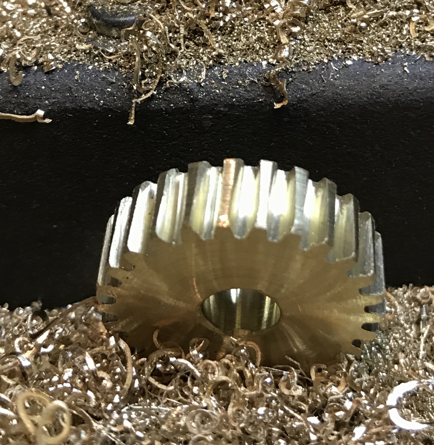
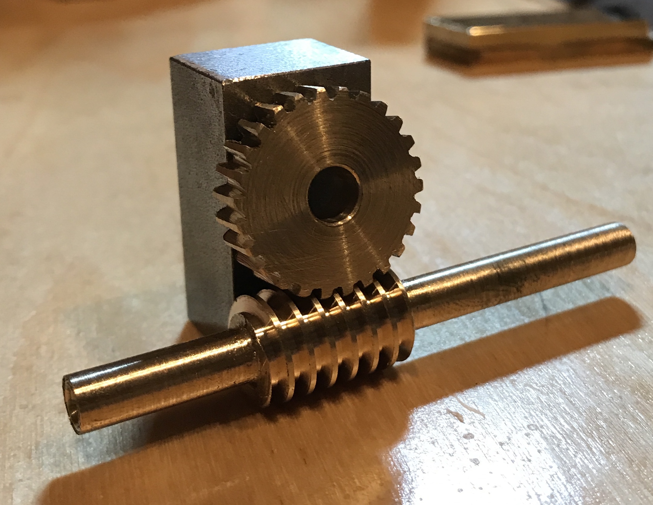
When changing the 100 tooth "B" gear it has to pressed off of the shaft on the attachment. This was done with a hammer and a 1/2" wooden dowel. The 50 tooth gear could then be pressed onto the same shaft. (Removing the 50 tooth gear later required a thin strip of stiff steel to work it up off the shaft.) The gear ratios were selected and the attachment was assembled after removing the motor. The 30° included angle cutter was first honed on a stone and then adjusted to center height in the Sherline tool holder. After adjusting the tool so it just "kissed" the part the tool was advanced 0.005" and the first cut was made. This was followed by 3-4 cuts at 0.003". A rhythm was then established with 0.002" cuts followed by a clean up pass. This was continued all the way to the 0.072" thread depth. Cutting fluid was applied for each 0.002" cut. No clean up was required as the threads looked perfect. As can be seen in the following photo the worm and wheel mate very nicely.
There were a few modifications that needed to be made to both the worm and wheel as made before they worked in the orrery. The 0.75" shaft on the worm had to be shortened, otherwise it bumped up against a spacer on the central gear shaft. It was sawn off with a hacksaw to leave 1/2". The end was cleaned up with a file. A flat was milled at the far end. The wheel needed a hole for the locking pin as it needs to "locked" to the other driving gears. The wheel was held in the mill vise and a #40 drill was used to put a 1/8" deep hole 0.350" from the center of the gear. The assembly was put back together with the new worm and wheel. Turning the handle leads to perfectly smooth gear rotation!!
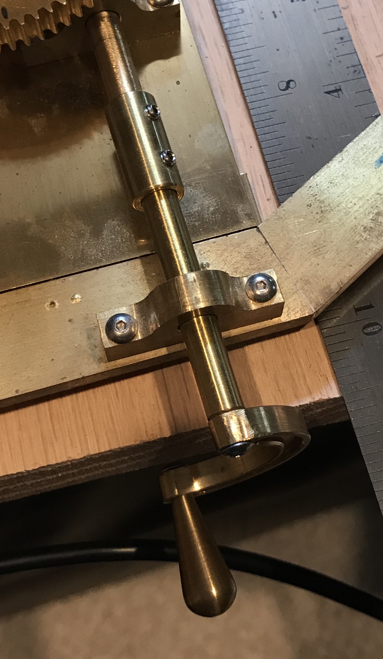
I've been thinking about the handle and its location relative to the base and the eventual glass dome covering the orrery. As the handle is configured now the outer edge of the orrery needs to be less than 1/2" from the edge of the base. This gives just barely enough room to put a groove in the base for the dome. The fact that a dome is planned implies that the handle must come off, when the dome is on. It does not make sense to keep a hex wrench in the dome to remove and attach the handle each time the orrery is adjusted. Currently, the handle is attached to a shaft by a screw. This shaft is attached to the worm shaft with a coupling. One possibility is to put a slot in the worm shaft and cut two flats on the other shaft turning it into a blade. Then the handle is easily removed and installed. The shaft for attaching the handle can be as long as needed to allow the handle to sit outside the base, when attached. A photo of the current handle attachment is below.